Intelligent Battery Sensor (IBS) Explanation

Fig 1

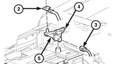
Fig 2
Fig 3
Fig 4
INTELLIGENT BATTERY SENSOR (IBS) DESCRIPTION
The Intelligent Battery Sensor (IBS) serves to record and process measured battery variable values (current, voltage, temperature) for the vehicle powernet management system. The Intelligent Battery Sensor (IBS) will calculate the Battery 'state of charge', 'state of health', and 'state of function'.
The mechanical part of the IBS is comprised of the battery clamp for the negative terminal and a captured bolt to attach the ground cable to. The functional tasks include establishing the electrical contact between the body and the negative battery post, housing the electronic module (actual sensor element) and the provision of an adequate thermal contact between the sensor system temperature sensor and the negative battery post. The mechanical part of the IBS also protects the sensitive electronic components from external influences.
The IBS is mounted directly on the 12 VDC battery's negative post. The battery post clamp nut is a captive nut and the stud will break if the nut is removed.
INTELLIGENT BATTERY SENSOR (IBS) OPERATION
The Intelligent Battery Sensor (IBS) contains a low value resistor, or shunt. The shunt creates voltage drop, which is read by an internal microcontroller to determine the current flow in and out of the battery. In addition to the shunt, the IBS contains a sensor to monitor the battery's temperature. Data gathered by the IBS, including temperature, voltage, and current measurements, are transmitted over a LIN communication bus to either the Body Control Module (BCM) or the Powertrain Control Module (PCM), depending on the application. The IBS serves two primary purposes. The first is to provide the Powertrain Control Module (or PCM) with both immediate and historical battery information, so the PCM can precisely control the charging system. Precise charging is important on a vehicle equipped with an Absorbent Glass Material (or AGM) battery, because they are especially sensitive to overcharging. The second purpose is to provide data to the BCM for operation of the load-shedding feature. A fused power circuit and the LIN bus are connected to the IBS though a two-terminal connector.
In addition to real-time measurements, the IBS transmits some calculated battery data over the LIN bus, including state of charge, state of health, and state of function. These values are calculated by storing measurements over time.
The battery sensor is readable/diagnosable via a "scan tool" that can display all of the available parameters needed for vehicle servicing or trouble shooting.
Information the Intelligent Battery Sensor (IBS) send out on the CAN Bus is
SOC = Battery state of charge (or SOC) is expressed as a percentage. The IBS calculates the SOC based on measured voltage, and charge and discharge rates. Therefore, SOC is not a direct percentage of battery voltage.
SOF = Battery State of Function: Battery state of function (or SOF) is a calculated prediction of the lowest voltage the battery will drop to during engine cranking.
The PCM and BCM use this calculated information to optimize vehicle power management for increased fuel efficiency. The data transmitted from IBS is interpreted and sent over the CAN network by the module connected the IBS's LIN bus.
When the IBS is powered up for the first time or is powered after a power disconnection, it enters a "recalibration" phase, where the IBS must recognize the type of battery and its characteristics and state. So in this phase the tolerances on the state functions (SOC, SOF) are greater than in normal working condition. When IBS is disconnected from the battery, the device loses its stored memory. When power is restored, the IBS starts a relearn process. Until the relearn process is complete, accurate battery
state information is unavailable to other vehicle systems. The IBS relearn process requires five normal, operator initiated starts with at least eight hours of engine off time between each start. Usually, the process takes a few days of vehicle operation to complete. Remember, the relearn process is restarted every time power is reconnected to the IBS. This has a major effect on the stop/start feature.
A Note about Stop/Start and the IBS - Stop/start operation places a heavy demand on the battery. So, during stop/start operation, the PCM boosts the charging system's output to immediately recharge the battery after a start. For example, on the Ram HFE, charging output is boosted to 220 amps. This very high charging rate would not be prudent without knowing detailed battery information, because the battery or charging system could be damaged. Also, the PCM does not have enough data to determine if the battery has enough power to restart the engine. So, stop/start is disabled during the IBS relearn mode. The EVIC displays various messages when the stop/start feature is disabled.
If the IBS is faulty it cannot be serviced, it must be replaced.
INTELLIGENT BATTERY SENSOR (IBS) REMOVAL
WARNING: Do not remove the captive nut, doing so will cause the stud to break.
1. Loosen the captive nut (Fig 2) #4.
2. Disconnect the electrical connector from the IBS (Fig 2) #3.
3. Remove the IBS sensor (Fig 2) #5 from the battery.
4. Remove the negative battery cable retainer (Fig 2) #1.
5. Remove the negative battery cable (Fig 2) #2 from the Intelligent Battery Sensor (IBS) #5.
INTELLIGENT BATTERY SENSOR (IBS) INSTALLATION
NOTE: Connecting the negative battery cable to the Intelligent Battery Sensor (IBS) must be done before installing on the battery post.
1. Install the negative battery cable to the IBS (Fig 2) #2.
2. Install the IBS negative battery cable retainer (Fig 2) #1. Tighten to 16 N.m (12 Ft. Lbs).
3. Install the IBS (Fig 2) #5 on the negative post of the battery.
4. Tighten the captive nut (Fig 2) #4 to 8 N.m (72 In. Lbs.).
5. Connect the IBS electrical connector (Fig 2) #3 to the IBS #5.


